
Page 169 - Mechatronic Systems Modelling and Simulation with HDLs
P. 169
158 7 MECHATRONICS
• Finally, when the product is with the customer, i.e. a disk drive company, or
even in the field, the analysis of spurious behaviour on the system model is
much easier for application engineers, since every signal or quantity is visible.
Unfortunately, this does not cover all possible faults of a device, since imple-
mentation related effects are not taken into account in system modelling. On
the other hand, with adequate fault modelling it should be easy to prove or
disprove any hypothesis that the application engineers may have on the root
cause of system failures.
In the following, this will be illustrated on the basis of the example of the servo
control of a disk drive system.
7.5.5 System modelling
A disk drive comprises digital and analogue/power electronics, firmware and
mechanics which — as pointed out before — results in three major interfaces:
hardware–software, analogue–digital and electronics–mechanics. These interfaces
have to be handled at the same time, which does not necessarily mean that
the complete drive has to be present in any system simulation, but for instance
when assessing the servo control for controlling the track following or seeking,
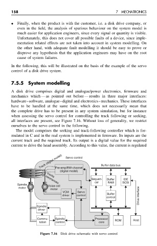
all interfaces are present, see Figure 7.16. Without loss of generality, we restrict
ourselves to the servo control in the following.
The model comprises the seeking and track-following controller which is for-
mulated in C and in the real system is implemented in firmware. Its inputs are the
current track and the required track. Its output is a digital value for the required
current to drive the head assembly. According to this value, the current is regulated
Track (digital model) Servo control Buffer data bus
Pre-amp/RW-channel
(digital model)
Inertia
Sequen- Buffer IDE
cer RAM SCSI
resonances
Spindle Voice coil
motor
motor
VCM Servo
driver control Buffer Drive interface
control
Spindle
driver
Commu- Spindle Processor ROM Host
tation control core
Figure 7.16 Disk drive schematic with servo control