
Page 171 - Mechatronic Systems Modelling and Simulation with HDLs
P. 171
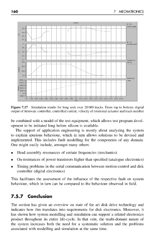
160                                                    7  MECHATRONICS


                                                 Graph0
                                                                              [V] : t(s)
                                                                              Control voltage
                     2.8
                     2.4
                   [V]
                     2.0
                     1.6
                                                                              [A] : t(s)
                     1.0
                                                                              Controlled current
                     0.5
                   [A]  0.0
                     −0.5
                    −1.0                                                      [rad/sec]: t(s)
                     60.0                                                     Velocity
                     40.0
                   [rad/sec]  20.0
                     0.0
                                                                              [#track]: t(s)
                   25000.0                                                    Track
                   20000.0
                   [#track] 15000.0
                   10000.0
                    5000.0
                     0.0
                   −5000.0
                       0.0  0.001 0.002 0.003  0.004  0.005  0.006  0.007 0.008  0.009  0.01  0.011 0.012  0.013  0.014  0.015 0.016  0.017  0.018 0.019
                                                  t(s)
               Figure 7.17 Simulation results for long seek over 20 000 tracks. From top to bottom: digital
               output of firmware controller, controlled current, velocity of rotational actuator and track-number

               be combined with a model of the test equipment, which allows test program devel-
               opment to be initiated long before silicon is available.
                 The support of application engineering is mostly about analyzing the system
               to explain spurious behaviour, which in turn allows solutions to be devised and
               implemented. This includes fault modelling for the components of any domain.
               One might easily include, amongst many others:

               •  Head assembly resonances of certain frequencies (mechanics)
               •  On-resistances of power transistors higher than specified (analogue electronics)
               •  Timing problems in the serial communication between motion-control and disk
                  controller (digital electronics)
               This facilitates the assessment of the influence of the respective fault on system
               behaviour, which in turn can be compared to the behaviour observed in field.


               7.5.7    Conclusion

               The section has given an overview on state of the art disk drive technology and
               indicates how this translates into requirements for disk electronics. Moreover, it
               has shown how system modelling and simulation can support a related electronics
               product throughout its entire life-cycle. In that vein, the multi-domain nature of
               the system increases both the need for a systematic solution and the problems
               associated with modelling and simulation at the same time.