
Page 175 - Mechatronic Systems Modelling and Simulation with HDLs
P. 175
164 8 MICROMECHATRONICS
and how the entire system can be designed and optimised. The methods of the first
category often form the basis for the consideration of the higher abstraction level.
8.1.2 Component design
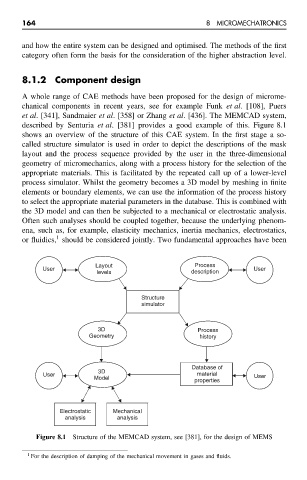
A whole range of CAE methods have been proposed for the design of microme-
chanical components in recent years, see for example Funk et al. [108], Puers
et al. [341], Sandmaier et al. [358] or Zhang et al. [436]. The MEMCAD system,
described by Senturia et al. [381] provides a good example of this. Figure 8.1
shows an overview of the structure of this CAE system. In the first stage a so-
called structure simulator is used in order to depict the descriptions of the mask
layout and the process sequence provided by the user in the three-dimensional
geometry of micromechanics, along with a process history for the selection of the
appropriate materials. This is facilitated by the repeated call up of a lower-level
process simulator. Whilst the geometry becomes a 3D model by meshing in finite
elements or boundary elements, we can use the information of the process history
to select the appropriate material parameters in the database. This is combined with
the 3D model and can then be subjected to a mechanical or electrostatic analysis.
Often such analyses should be coupled together, because the underlying phenom-
ena, such as, for example, elasticity mechanics, inertia mechanics, electrostatics,
1
or fluidics, should be considered jointly. Two fundamental approaches have been
Layout Process
User User
levels description
Structure
simulator
3D Process
Geometry history
Database of
3D
User material User
Model
properties
Electrostatic Mechanical
analysis analysis
Figure 8.1 Structure of the MEMCAD system, see [381], for the design of MEMS
1 For the description of damping of the mechanical movement in gases and fluids.