
Page 180 - Mechatronic Systems Modelling and Simulation with HDLs
P. 180
8.2 DEMONSTRATOR 5: CAPACITIVE PRESSURE SENSOR 169
ANSYS. Thus, as shown later in the simulation experiments, the mechanical
behaviour cannot be distinguished from that simulated using ANSYS.
Setting up the element matrices
Now, the finite element to be formulated in a hardware description language should
be parametrisable with regard to its dimensions and the associated material con-
stants. Furthermore, the model should also be suitable for greater deflections. Both
cases require that the element matrices must be constructed in the model of the
finite elements. In this way the approach described here, see [333] and [33], differs
significantly from the (later) work of Haase et al. [131] in which a system matrix of
the mechanics constructed using a FE simulator is imported into a circuit simulator
via a hardware description language.
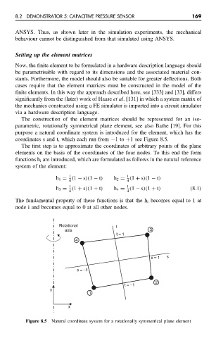
The construction of the element matrices should be represented for an iso-
parametric, rotationally symmetrical plane element, see also Bathe [19]. For this
purpose a natural coordinate system is introduced for the element, which has the
coordinates s and t, which each run from −1to +1 see Figure 8.5.
The first step is to approximate the coordinates of arbitrary points of the plane
elements on the basis of the coordinates of the four nodes. To this end the form
functions h i are introduced, which are formulated as follows in the natural reference
system of the element:
1
1
h 1 = (1 − s)(1 − t) h 2 = (1 + s)(1 − t)
4 4
1
1
h 3 = (1 + s)(1 + t) h 4 = (1 − s)(1 + t) (8.1)
4 4
The fundamental property of these functions is that the h i becomes equal to 1 at
node i and becomes equal to 0 at all other nodes.
Rotational t
axis 3
t = 1
4
s = 1 s
s = −1
2
t = −1
y
1
x
Figure 8.5 Natural coordinate system for a rotationally symmetrical plane element