
Page 179 - Mechatronic Systems Modelling and Simulation with HDLs
P. 179
168 8 MICROMECHATRONICS
y (axial) L K
I J
x (radial)
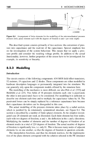
Figure 8.4 Arrangement of finite elements for the modelling of the micromechanical pressure
element (left); plane element each with the degrees of freedom u and v per node (right)
The described system consists primarily of two sections: the conversion of pres-
sure into capacitance and the read-out of the capacitance. Special emphasis lies
on the investigation of the system behaviour. This means that we apply a pres-
sure profile and consider the resulting voltage profile. In addition to the actual
functionality, however, further properties of the sensor have to be investigated; for
example, its sensitivity or linearity.
8.2.2 Modelling
Introduction
The circuit consists of the following components: 634 MOS field effect transistors,
52 resistors, 19 capacitors and 12 diodes. These components are either modelled in
hardware description languages or permanently integrated into the simulator. We
can generally rely upon the component models offered by the simulator here.
The modelling of the mechanics is more difficult, see also Pelz et al. [333] and
Bielefeld et al. [33]. Two fields of 18 pressure elements each–one is passivated,
the other is non-passivated–have to be considered. For modelling it is sufficient to
describe one element each time and to multiply the capacitance values by 18. The
passivated boxes can be simply replaced by a reference capacitance here because
their capacitance deviation can be disregarded in this case.
The actual modelling of the pressure elements takes place by a radial section,
which is justified by its rotationally symmetrical structure, see Figure 8.4. The
section is described by a number of finite (plane) elements. In the simplest investi-
gated case 28 elements are used, as illustrated. Each finite element has four nodes,
each with two degrees of freedom, u and v, the deflection in the x and y directions.
Multiplying the number of elements and the number of degrees of freedom of an
element results in a total of 224 degrees of freedom. The actual number of degrees
of freedom is significantly less, i.e. only 81. This is because many nodes of adjacent
elements lie on one another, so that the degrees of freedom in question coincide.
The interpolation functions, and thus the element matrices, for the implementa-
tion of the plane element correspond with the solution selected in the FE simulator