
Page 184 - Mechatronic Systems Modelling and Simulation with HDLs
P. 184
8.2 DEMONSTRATOR 5: CAPACITIVE PRESSURE SENSOR 173
This is based upon a library of matrix operations. As the following section shows,
the C routines for element stiffness matrix and element mass matrix are called
up from the hardware description, in order to determine the matrices in question.
The above-mentioned operations for the creation of the element matrices should
be performed at least once at the beginning of the simulation and several times in
the event of greater deflections or nonlinearities.
Formulation in a hardware description language
The finite plane element called plane_u2 described in the previous sections will
now be formulated in an analogue hardware description language, see Hardware
description 8.1. The MAST language has been selected for this. Two aspects have
to be taken care of: the creation of the mass and stiffness matrices of the elements
dealt with in the previous section and the linking of the mechanics thus described
into a circuit simulation, see Chapter 6.
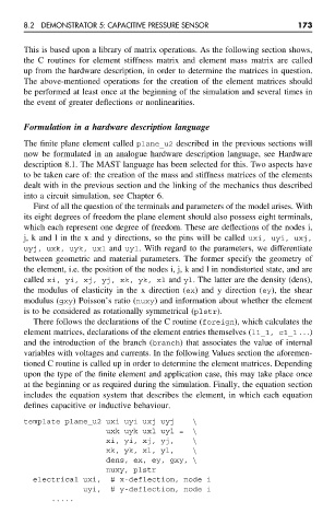
First of all the question of the terminals and parameters of the model arises. With
its eight degrees of freedom the plane element should also possess eight terminals,
which each represent one degree of freedom. These are deflections of the nodes i,
j, k and l in the x and y directions, so the pins will be called uxi, uyi, uxj,
uyj, uxk, uyk, uxl and uyl. With regard to the parameters, we differentiate
between geometric and material parameters. The former specify the geometry of
the element, i.e. the position of the nodes i, j, k and l in nondistorted state, and are
called xi, yi, xj, yj, xk, yk, xl and yl. The latter are the density (dens),
the modulus of elasticity in the x direction (ex) and y direction (ey), the shear
modulus (gxy) Poisson’s ratio (nuxy) and information about whether the element
is to be considered as rotationally symmetrical (plstr).
There follows the declarations of the C routine (foreign), which calculates the
element matrices, declarations of the element entries themselves (l1_1, c1_1 ...)
and the introduction of the branch (branch) that associates the value of internal
variables with voltages and currents. In the following Values section the aforemen-
tioned C routine is called up in order to determine the element matrices. Depending
upon the type of the finite element and application case, this may take place once
at the beginning or as required during the simulation. Finally, the equation section
includes the equation system that describes the element, in which each equation
defines capacitive or inductive behaviour.
template plane_u2 uxi uyi uxj uyj \
uxk uyk uxl uyl = \
xi, yi, xj, yj, \
xk, yk, xl, yl, \
dens, ex, ey, gxy, \
nuxy, plstr
electrical uxi, # x-deflection, node i
uyi, # y-deflection, node i
.....