
Page 187 - Mechatronic Systems Modelling and Simulation with HDLs
P. 187
176 8 MICROMECHATRONICS
form of variable capacitors, is positioned between the two plate potentials and is
thus available to the circuit.
8.2.3 Simulation
In the following, various simulations will be performed in order to illustrate the
application of finite elements for a circuit simulator. The following cases will
be considered here: mechanical deflections, changes of the element capacitance,
system simulation and the parametrised simulation of the FE models. A FE model
of the sensor structure based upon 48 finite elements was used.
Mechanical behaviour
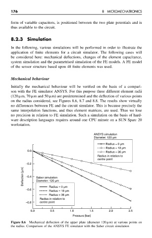
Initially the mechanical behaviour will be verified on the basis of a compari-
son with the FE simulator ANSYS. For this purpose three different element radii
(120 µm, 70 µm and 50 µm) are predetermined and the deflection of various points
on the radius considered, see Figures 8.6, 8.7 and 8.8. The results show virtually
no differences between FE and the circuit simulator. This is because precisely the
same interpolation functions, and thus element matrices, are used. Thus we lose
no precision in relation to FE simulation. Such a simulation on the basis of hard-
ware description languages requires around one CPU minute on a SUN Sparc 20
workstation.
ANSYS simulation
Diameter: 120 µm
Radius = 0 µm
Radius = 18 µm
0.0 Radius = 36 µm
Radius in relation to
centre point
−0.2
Deflection [µm] −0.4 Saber simulation
Diameter: 120 µm
Radius = 0 µm
−0.6
Radius = 18 µm
Radius = 36 µm
Radius in relation to
−0.8 centre point
0.0 0.5 1.0 1.5 2.0 2.5
Pressure [bar]
Figure 8.6 Mechanical deflection of the upper plate (diameter 120 µm) at various points on
the radius. Comparison of the ANSYS FE simulator with the Saber circuit simulation