
Page 188 - Mechatronic Systems Modelling and Simulation with HDLs
P. 188
8.2 DEMONSTRATOR 5: CAPACITIVE PRESSURE SENSOR 177
ANSYS simulation
Diameter: 70 µm
Radius = 0 µm
0.0 Radius = 10.5 µm
Radius = 21 µm
Radius in relation
to centre point
−0.2
Deflection [µm] −0.4 Saber simulation
Diameter: 70 µm
Radius = 0 µm
−0.6
Radius = 10.5 µm
Radius = 21 µm
Radius in relation
−0.8 to centre point
0 5 10 15 20
Pressure [bar]
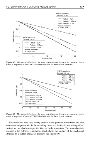
Figure 8.7 Mechanical deflection of the upper plate (diameter 70 µm) at various points on the
radius. Comparison of the ANSYS FE simulator with the Saber circuit simulator
ANSYS simulation
Diameter: 50 µm
Radius = 0 µm
0.0 Radius = 7.5 µm
Radius = 15 µm
Radius in relation
−0.2 to centre point
Deflection [µm] −0.4 Saber simulation
Diameter: 50 µm
−0.6 Radius = 0 µm
Radius = 7.5 µm
Radius = 15 µm
Radius in relation
−0.8 to centre point
0 10 20 30 40 50 60
Pressure [bar]
Figure 8.8 Mechanical deflection of the upper plate (diameter 50 µm) at various points on the
radius. Comparison of the ANSYS FE simulator with the Saber circuit simulator
The mechanics was very slowly excited in the previous simulations and thus
considered as quasi-static. In the modelling, however, the inertia was also specified,
so that we can also investigate the kinetics in the simulation. This was taken into
account in the following simulation, which shows the reaction of the mechanical
structure to a sudden change of pressure, see Figure 8.9.