
Page 190 - Mechatronic Systems Modelling and Simulation with HDLs
P. 190
8.2 DEMONSTRATOR 5: CAPACITIVE PRESSURE SENSOR 179
which acts as a mechanical stop and thus causes a geometric nonlinearity. In
particular, various natural frequencies are excited as a result of the collision, which
is particularly evident from the displacement in the x-direction. It is clear that this
type of simulation permits the consideration of the electro-mechanical dynamics
in a transient simulation. Furthermore we can read off the most important natural
frequencies from such a simulation.
Electrical behaviour
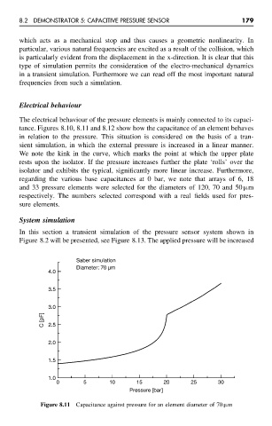
The electrical behaviour of the pressure elements is mainly connected to its capaci-
tance. Figures 8.10, 8.11 and 8.12 show how the capacitance of an element behaves
in relation to the pressure. This situation is considered on the basis of a tran-
sient simulation, in which the external pressure is increased in a linear manner.
We note the kink in the curve, which marks the point at which the upper plate
rests upon the isolator. If the pressure increases further the plate ‘rolls’ over the
isolator and exhibits the typical, significantly more linear increase. Furthermore,
regarding the various base capacitances at 0 bar, we note that arrays of 6, 18
and 33 pressure elements were selected for the diameters of 120, 70 and 50 µm
respectively. The numbers selected correspond with a real fields used for pres-
sure elements.
System simulation
In this section a transient simulation of the pressure sensor system shown in
Figure 8.2 will be presented, see Figure 8.13. The applied pressure will be increased
Saber simulation
Diameter: 70 µm
4.0
3.5
3.0
C [pF] 2.5
2.0
1.5
1.0
0 5 10 15 20 25 30
Pressure [bar]
Figure 8.11 Capacitance against pressure for an element diameter of 70 µm