
Page 194 - Mechatronic Systems Modelling and Simulation with HDLs
P. 194
8.3 DEMONSTRATOR 6: MICROMIRROR 183
this micromirror, see K¨ uck et al. [209], is a system manufactured using CMOS
compatible surface micromechanics. It is operated as an actuator, i.e. the mechan-
ical displacement is not the object of the measurement, but rather the system
behaviour to be caused. Here the deflection consists of the lowering of the mirror.
If light falls on the mirror its deflection brings about a corresponding phase shift
in the reflected light. The picture to be generated finally arises from the resulting
interferences. The deflection is achieved electrostatically.
8.3.1 System description
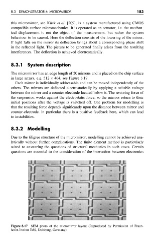
The micromirror has an edge length of 20 microns and is placed on the chip surface
in large arrays, e.g. 512 × 464, see Figure 8.17.
Each mirror is individually addressable and can be moved independently of the
others. The mirrors are deflected electrostatically by applying a suitable voltage
between the mirror and a counter-electrode located below it. The restoring force of
the suspension works against the electrostatic force, so the mirrors return to their
initial positions after the voltage is switched off. One problem for modelling is
that the resulting force depends significantly upon the distance between mirror and
counter-electrode. In particular there is a positive feedback here, which can lead
to instabilities.
8.3.2 Modelling
Due to the filigree structure of the micromirror, modelling cannot be achieved ana-
lytically without further complications. The finite element method is particularly
suited to answering the questions of structural mechanics in such cases. Certain
questions are essential to the consideration of the interaction between electronics
Figure 8.17 SEM photo of the micromirror layout (Reproduced by Permission of Fraun-
hofer-Institut IMS, Duisburg, Germany)