
Page 195 - Mechatronic Systems Modelling and Simulation with HDLs
P. 195
184 8 MICROMECHATRONICS
and mechanics. Initially the relationship between the voltage applied and the result-
ing deflection should of course be investigated. Furthermore, the feedback of the
mirror capacitance on the electronics and the possible excitation of resonances of
the mirror is also of interest. Figure 8.19 shows the typical deflection of a micromir-
ror and the structure of the associated FE model. This is based upon plate elements,
which are particularly well suited for the layer structure of micromechanics. The
following representation deals with rectangular plate elements, which are treated in
detail in Gasch and Knothe et al. [113]. The description of modelling is dealt with
more briefly here in comparison with the previous demonstrator because — like
the beams introduced in Chapter 6 — small deflections result in constant mass and
stiffness matrices for the rectangular plate elements used. Furthermore, the cus-
tomisation of the element matrices according to geometric and material parameters
is very simple in this case.
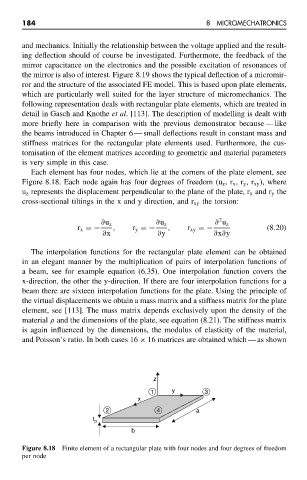
Each element has four nodes, which lie at the corners of the plate element, see
Figure 8.18. Each node again has four degrees of freedom (u z ,r x ,r y ,r xy ), where
u z represents the displacement perpendicular to the plane of the plate, r x and r y the
cross-sectional tiltings in the x and y direction, and r xy the torsion:
2
∂u z ∂u z ∂ u z
r x =− , r y =− , r xy =− (8.20)
∂x ∂y ∂x∂y
The interpolation functions for the rectangular plate element can be obtained
in an elegant manner by the multiplication of pairs of interpolation functions of
a beam, see for example equation (6.35). One interpolation function covers the
x-direction, the other the y-direction. If there are four interpolation functions for a
beam there are sixteen interpolation functions for the plate. Using the principle of
the virtual displacements we obtain a mass matrix and a stiffness matrix for the plate
element, see [113]. The mass matrix depends exclusively upon the density of the
material ρ and the dimensions of the plate, see equation (8.21). The stiffness matrix
is again influenced by the dimensions, the modulus of elasticity of the material,
and Poisson’s ratio. In both cases 16 × 16 matrices are obtained which — as shown
z
1 y 3
x
2 4 a
t p
b
Figure 8.18 Finite element of a rectangular plate with four nodes and four degrees of freedom
per node