
Page 197 - Mechatronic Systems Modelling and Simulation with HDLs
P. 197
186 8 MICROMECHATRONICS
0
Saber
−20
Ansys
−40
U z −60
−80
−100
−120
0 5 10 15 20 25 30
V /V
ex
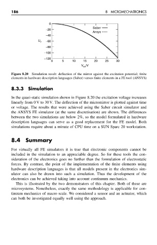
Figure 8.20 Simulation result: deflection of the mirror against the excitation potential; finite
elements in hardware description languages (Saber) versus finite elements in a FE tool (ANSYS)
8.3.3 Simulation
In the quasi-static simulation shown in Figure 8.20 the excitation voltage increases
linearly from 0 V to 30 V. The deflection of the micromirror is plotted against time
or voltage. The results that were achieved using the Saber circuit simulator and
the ANSYS FE simulator (at the same discretisation) are shown. The differences
between the two simulations are below 2%, so the model formulated in hardware
description languages can serve as a good replacement for the FE model. Both
simulations require about a minute of CPU time on a SUN Sparc 20 workstation.
8.4 Summary
For virtually all FE simulators it is true that electronic components cannot be
included in the simulation to an appreciable degree. So for these tools the con-
sideration of the electronics goes no further than the formulation of electrostatic
forces. By contrast, the point of the implementation of the finite elements using
hardware description languages is that all models present in the electronics sim-
ulator can also be drawn into such a simulation. Thus the development of the
electronics can be achieved taking into account continuum mechanics.
This is illustrated by the two demonstrators of this chapter. Both of these are
microsystems. Nonetheless, exactly the same methodology is applicable for con-
tinuum mechanics of macro scale. We considered a sensor and an actuator, which
can both be investigated equally well using the approach.