
Page 196 - Mechatronic Systems Modelling and Simulation with HDLs
P. 196
8.3 DEMONSTRATOR 6: MICROMIRROR 185
0
−50
z/nm −100
5 10
−10 0
−5 0 5
5 10
x/µm 10 y/µm
(a) (b)
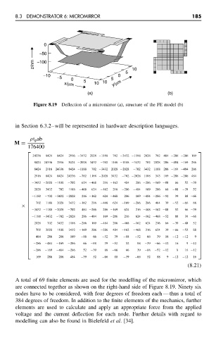
Figure 8.19 Deflection of a micromirror (a), structure of the FE model (b)
in Section 6.3.2–will be represented in hardware description languages.
ρt p ab
M =
176400
24336 8424 8424 2916 −3432 2028 −1188 702 −3432 −1188 2028 702 484 −286 −286 169
8424 24336 2916 8424 −2028 3432 −702 1188 −1188 −3432 702 2028 286 −484 −169 286
8424 2916 24336 8424 −1188 702 −3432 2028 −2028 −702 3432 1188 286 −169 −484 286
2916 8424 8424 24336 −702 1188 −2028 3432 −702 −2028 1188 343 169 −286 −286 484
−3432 −2028 −1188 −702 624 −468 216 −162 484 286 −286 −169 −88 66 52 −39
2028 3432 702 1188 −468 624 −162 216 −286 −484 169 286 66 −88 −39 52
−1188 −702 −3432 −2028 216 −162 624 −468 286 169 −484 −286 −52 39 88 −66
702 1188 2028 3432 −162 216 −468 624 −169 −286 286 484 39 −52 −66 88
×
−3432 −1188 −2028 −702 484 −286 286 −169 624 216 −468 −162 −88 52 66 −39
−1188 −3432 −702 −2028 286 −484 169 −286 216 624 −162 −468 −52 88 39 −66
2028 702 3432 1188 −286 169 −484 286 −468 −162 624 216 66 −39 −88 52
702 2028 1188 3432 −169 286 −286 484 −162 −468 216 624 39 −66 −52 88
484 286 286 169 −88 66 −52 39 −88 −52 66 39 16 −12 −12 9
−286 −484 −169 −286 66 −88 39 −52 52 88 −39 −66 −12 16 9 −12
−286 −169 −484 −286 52 −39 88 −66 66 39 −88 −52 −12 9 16 −12
169 286 286 484 −39 52 −66 88 −39 −66 52 88 9 −12 −12 16
(8.21)
A total of 69 finite elements are used for the modelling of the micromirror, which
are connected together as shown on the right-hand side of Figure 8.19. Ninety six
nodes have to be considered, with four degrees of freedom each — thus a total of
384 degrees of freedom. In addition to the finite elements of the mechanics, further
elements are used to calculate and apply an appropriate force from the applied
voltage and the current deflection for each node. Further details with regard to
modelling can also be found in Bielefeld et al. [34].