
Page 185 - Mechatronic Systems Modelling and Simulation with HDLs
P. 185
174 8 MICROMECHATRONICS
number xi = 0.0, # x-coordinate, node i
yi = 0.0, # y-coordinate, node i
.....
number dens = 0.0, # Density
.....
{
foreign planeu2 # C function
....
val nu l1_2,l1_3,l1_4, # L coefficient
....
c1_1,c1_3, # C coefficient
....
# Definition of branch voltages and currents
# at node uxi
branch i1_1a = i(uxi->gnd), \
v1_1 = v(uxi,gnd)
....
....
# at node uyl
branch i8_8a = i(uyl->gnd), \
v8_8 = v(uyl,gnd)
# Call up of the external C function for the calculation
# of the mass and stiffness matrix of the element
values{
...
(l1_2,l1_3,...... \
c1_1,c1_3,.....) = \
plane_u2 (xi, yi, .....)
...
}
# Definition of the dynamic equations
equations{
i1_1a = d_by_dt(v1_1 * c1_1)
v1_2 = d_by_dt(i1_2b * l1_2)
....
i8_8a = d_by_dt(v8_8 * c8_8)
}
}
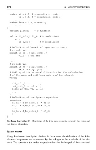
Hardware description 8.1 Description of the finite plane elements, each with four nodes and
two degrees of freedom
System matrix
Using the element description obtained in this manner the deflections of the finite
elements in question are represented by the voltages at the terminals of the ele-
ment. The currents at the nodes in question describe the integral of the associated