
Page 167 - Mechatronic Systems Modelling and Simulation with HDLs
P. 167
156 7 MECHATRONICS
Circuits Function Implementation
Motion- Spindle Custom
control control power
Harddisk- Servo Custom
controller control analog
Signal Cores &
Channel
processing firmware
Pre-amp Buffer Custom
manager digital
Host
DRAM Memory
interface
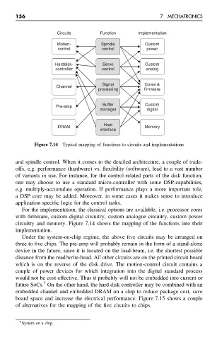
Figure 7.14 Typical mapping of functions to circuits and implementations
and spindle control. When it comes to the detailed architecture, a couple of trade-
offs, e.g. performance (hardware) vs. flexibility (software), lead to a vast number
of variants in use. For instance, for the control-related parts of the disk function,
one may choose to use a standard micro-controller with some DSP-capabilities,
e.g. multiply-accumulate operation. If performance plays a more important role,
a DSP core may be added. Moreover, in some cases it makes sense to introduce
application specific logic for the control tasks.
For the implementation, the classical options are available, i.e. processor cores
with firmware, custom digital circuitry, custom analogue circuitry, custom power
circuitry and memory. Figure 7.14 shows the mapping of the functions into their
implementation.
Under the system-on-chip regime, the above five circuits may be arranged on
three to five chips. The pre-amp will probably remain in the form of a stand-alone
device in the future, since it is located on the load-beam, i.e. the shortest possible
distance from the read/write-head. All other circuits are on the printed circuit board
which is on the reverse of the disk drive. The motion-control circuit contains a
couple of power devices for which integration into the digital standard process
would not be cost-effective. Thus it probably will not be embedded into current or
7
future SoCs. On the other hand, the hard disk controller may be combined with an
embedded channel and embedded DRAM on a chip to reduce package cost, save
board space and increase the electrical performance. Figure 7.15 shows a couple
of alternatives for the mapping of the five circuits to chips.
7 System on a chip.