
Page 161 - Mechatronic Systems Modelling and Simulation with HDLs
P. 161
150 7 MECHATRONICS
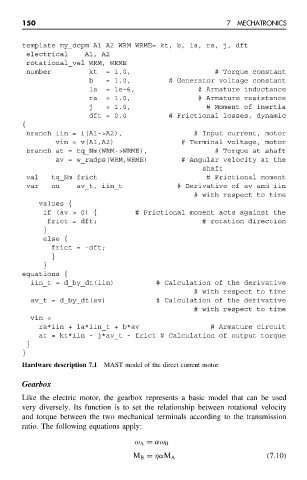
template my_dcpm A1 A2 WRM WRME= kt, b, la, ra, j, dft
electrical A1, A2
rotational_vel WRM, WRME
number kt = 1.0, # Torque constant
b = 1.0, # Generator voltage constant
la = 1e-6, # Armature inductance
ra = 1.0, # Armature resistance
j = 1.0, # Moment of inertia
dft = 0.0 # Frictional losses, dynamic
{
branch iin = i(A1->A2), # Input current, motor
vin = v(A1,A2) # Terminal voltage, motor
branch at = tq_Nm(WRM->WRME), # Torque at shaft
av = w_radps(WRM,WRME) # Angular velocity at the
shaft
val tq_Nm frict # Frictional moment
var nu av_t, iin_t # Derivative of av and iin
# with respect to time
values {
if (av > 0) { # Frictional moment acts against the
frict = dft; # rotation direction
}
else {
frict = -dft;
}
}
equations {
iin_t = d_by_dt(iin) # Calculation of the derivative
# with respect to time
av_t = d_by_dt(av) # Calculation of the derivative
# with respect to time
vin =
ra*iin + la*iin_t + b*av # Armature circuit
at = kt*iin - j*av_t - frict # Calculation of output torque
}
}
Hardware description 7.1 MAST model of the direct current motor
Gearbox
Like the electric motor, the gearbox represents a basic model that can be used
very diversely. Its function is to set the relationship between rotational velocity
and torque between the two mechanical terminals according to the transmission
ratio. The following equations apply:
ω A = αω B
M B = ηαM A (7.10)