
Page 156 - Mechatronic Systems Modelling and Simulation with HDLs
P. 156
7.3 DEMONSTRATOR 2: INTERNAL COMBUSTION ENGINE WITH DRIVE TRAIN 145
exhaust blocks supply a broad overview of the current NO x , CO and HC values
of the engine, which are obtained from λ and a ig .
7.3.2 Modelling
At this point some of the above-mentioned blocks will be described. We begin with
the generation of torque by an internal combustion engine. The underlying process
represents the conversion of chemical into mechanical energy. The input quantities
are the air mass m air , the fuel mixture ratio λ, the ignition advance angle a ig , and the
engine speed at the crankshaft n cs . We could start by deriving the resulting torque
M from the average pressure in the cylinder p m and the piston-swept volume V D ,
see [39]:
V D · p m
M = (7.5)
2π
However, the average pressure in the cylinder cannot easily be determined from
the input quantities. Rather, p m depends upon the combustion process, which takes
place in three spatial dimensions. Also problematic is the irregular shape of the
combustion space, which furthermore continuously changes shape. Finally, turbu-
lence effects in the mixture of air and fuel often cannot be disregarded. Thus the
physical modelling is separated from the consideration of the system as a whole.
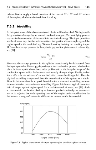
Since in this case there is no good foundation for a structural modelling, we now
turn our attention to experimental modelling. Figure 7.6 shows a typical character-
istic of torque against engine speed for a predetermined air mass, see [39]. Such
a characteristic can be described by an inverted parabola, whereby its parameters
are to be adjusted for each operating case of the engine under consideration. In
this context a range of values for different air masses should be recorded.
Torque [Nm]
150
130
110
90
70
1000 2000 3000 4000 5000
−1
Engine speed [min]
Figure 7.6 Typical characteristic of torque against engine speed for a given air mass