
Page 160 - Mechatronic Systems Modelling and Simulation with HDLs
P. 160
7.4 DEMONSTRATOR 3: CAMERA WINDER 149
Power
MOS Electric Gearbox Mechanical
load
motor Angular velocity /
+ Battery torque
pack
Power
− MOS Angular velocity
→ angle
Angle / torque
Switch-off
sensor
Mechanical
stop
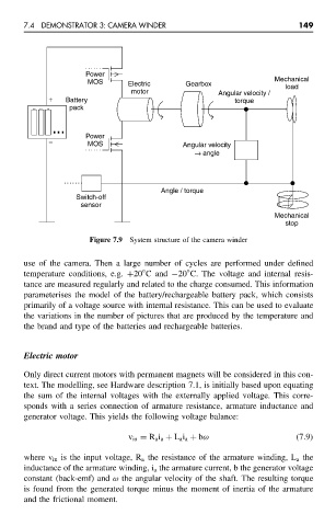
Figure 7.9 System structure of the camera winder
use of the camera. Then a large number of cycles are performed under defined
◦
◦
temperature conditions, e.g. +20 C and −20 C. The voltage and internal resis-
tance are measured regularly and related to the charge consumed. This information
parameterises the model of the battery/rechargeable battery pack, which consists
primarily of a voltage source with internal resistance. This can be used to evaluate
the variations in the number of pictures that are produced by the temperature and
the brand and type of the batteries and rechargeable batteries.
Electric motor
Only direct current motors with permanent magnets will be considered in this con-
text. The modelling, see Hardware description 7.1, is initially based upon equating
the sum of the internal voltages with the externally applied voltage. This corre-
sponds with a series connection of armature resistance, armature inductance and
generator voltage. This yields the following voltage balance:
v in = R a i a + L a i a + bω (7.9)
where v in is the input voltage, R a the resistance of the armature winding, L a the
inductance of the armature winding, i a the armature current, b the generator voltage
constant (back-emf) and ω the angular velocity of the shaft. The resulting torque
is found from the generated torque minus the moment of inertia of the armature
and the frictional moment.