
Page 97 - Mechatronic Systems Modelling and Simulation with HDLs
P. 97
86 5 SOFTWARE IN HARDWARE DESCRIPTION LANGUAGES
main(argc,argv)
int argc;
char argv[]; Mem PIO
{
int i, j, stat;
double v1, v2;
...
while (true) {
v1 = mem[pio];
if (v1 > THRESH) {
if (!check(v1))
continue;
stat = getstat();
if (stat == 0) CPU
putstat(HARD);
...
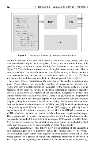
Figure 5.2 Execution of software by simulation at controller level
bus traffic between CPU and main memory, like many other details, does not
contribute significantly to the investigation of the system as a whole. Rather, it is
virtually always sufficient to imitate the interface behaviour of the controller, see
Figure 5.2. This facilitates a whole range of simplifications in the model. Thus it
may be possible to represent the memory primarily by an array of integer numbers
or bit vectors. Memory access can be formulated as access to the array. The data
and address bus and the associated logic are thus dispensed with completely.
In a more precise consideration, the objective of the model in question also
alters. Where before it was primarily a question of describing the hardware cor-
rectly, now such a model becomes an interpreter for the running software. This is
beneficial in two respects. Firstly, the model is significantly simplified, secondly
there is a considerable acceleration of the simulation. Interpretative models with
various characteristics exist. For example, Gupta et al. [130] link an interpretative
software simulator to the simulator responsible for the hardware for each simulator
coupling, taking into account cyclically correct timing. Furthermore, Ecker outlines
the formulation of a software interpreter in VHDL, see [92], in which precise timing
is largely disregarded. Finally, Pelz et al. [326], [327] suggest a cyclically correct
implementation of a software interpreter for the Motorola 68HC05 architecture in
VHDL, which is coupled to mechanics models in hardware description languages.
This approach will be described in more detail in what follows. It offers a simula-
tion speed of around 5000 assembler instructions per CPU second on a SUN-Sparc
20. Thus the performance of the simulation lies above that of the method described
in the previous paragraph by approximately an order of magnitude.
Hardware description 5.1 that follows provides an example of the description
of a (fictitious) processor at interpreter level. The characteristics of the proces-
sor architecture largely relate to the register variables and the command set. The
model consists of a process in which one assembler instruction is executed in
each loop. At the beginning the instruction is fetched from the main memory,