
Page 227 - Membranes for Industrial Wastewater Recovery and Re-Use
P. 227
196 Membranes for lndustrial Wastewater Recovery and Re-use
0 50 IO0 150 200 250 300 350 400
Mass load [th]
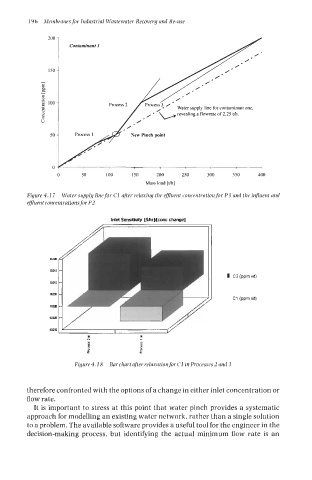
Figure 4.1 7 Water supply linefor C1 after relaxing the efluent roncentrationfor P3 and the influent and
efluent concentrations for P2
om
om5
om
om5
om
4ms
4mo
P
I
Figure4.18 Bar chart after relaxationfor C1 in Processes 2 and 3
therefore confronted with the options of a change in either inlet concentration or
flow rate.
It is important to stress at this point that water pinch provides a systematic
approach for modelling an existing water network, rather than a single solution
to a problem. The available software provides a useful tool for the engineer in the
decision-making process, but identifying the actual minimum flow rate is an