
Page 270 - Membranes for Industrial Wastewater Recovery and Re-Use
P. 270
Case studies 2 39
dissolved minerals and provide high-purity water to the boiler. The mixed water
flows through a reverse osmosis plant operating at a recovery of 80% and an
average salt rejection of 95%). Permeate from the RO mixes with product water
from both the waste RO unit and the distillate from the brine evaporator/
crystalliser situated in the wastewater treatment plant. The combined flow then
enters a degasifier, to remove carbon dioxide, and a mixed bed dimineraliser. The
mixed bed plant consists of two 100% capacity ion exchange vessels which
remove the final 5% of the dissolved salts. The ion exchange beds process
2 200 000 gallons (832 7 m3) before being regenerated. Waste from the process is
pH adjusted and combined with the RO reject before being pumped to the
wastewater treatment plant.
Wastewater treatment
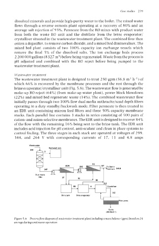
The wastewater treatment plant is designed to treat 250 gpm (56.8 m3 h-') of
which 66% is recovered by the membrane processes and the rest through the
brine evaporator/crystalliser unit (Fig. 5.6). The wastewater flow is generated by
make-up RO reject (64%) (from make-up water plant), power block blowdown
(22%) and mixed bed regenerate waste (14%). The combined wastewater flow
initially passes through two 100% flow dual media anthracite/sand depth filters
operating in a duty standby/backwash mode. Filter permeate is then treated in
an EDR unit containing micron feed filters and three 50%) capacity membrane
stacks. Each parallel line contains 3 stacks in series consisting of 500 pairs of
cation- and anion-selective membranes. The EDR unit is designed to recover 84%
of the flow with the remaining 16% being sent to the brine tank. The EDR unit
includes acid injection for pH control, anti-scalant and clean in place systems to
control fouling. The three stages in each stack are operated at voltages of 299,
344, and 264 V with corresponding currents of 17, 11 and 4.8 amps
Waste water
250
n
k 246.8
uu
Brine lank Brine evawrator
Fib press
t
t
Solids
Solids
(385 bs
(385 bs.h-') h.?)
Figure 5.6 Processflow diagram of wastewater treatment plant including a mass balance (gpm) based on 24
average during continuous operation