
Page 271 - Membranes for Industrial Wastewater Recovery and Re-Use
P. 271
240 Membranes for Industrial Wastewater Recovery and Re-use
respectively. The feed pump discharges at a pressure of 81 psi (5.6 bar) with a
differential pressure across the stacks of 14 psi (0.96 bar) on the positive side and
18 psi (1.24 bar) on the negative.
The flow then enters a reverse osmosis plant containing three parallel streams
designed at 50% flow enabling continuous operation. Each stream contains 24
cellulose acetate membranes arranged in a 4:2 array. The plant operates at an
overall recovery of 75% and a salt rejection of 95%. Permeate is pumped to the
demineralisation storage tank and reject is sent to the brine storage tank where it
is mixed with the EDR reject.
Treatment of the brine is conducted in a vertical tube, falling film evaporator
driven by vapour compression. Wastewater is pH adjusted to between 5.5 and 6
and then heated to boiling point and deaerated. Hot brine then enters the
evaporator sump where it mixes with recirculating brine slurry which is pumped
to the top of 2 inch (50.8 mm) heat transfer tubes. As the slurry falls a small
portion of the water evaporates and condenses on the outside of the heat transfer
tubes. The brine evaporator recovers 95%) of the flow which is passed on to the
demineralisation feed tank with a water quality of less than 10 ppm TDS. The 5%
concentrated brine then enters a crystalliser where a further 95% of the
remaining water is recovered. The stream is finally sent to a filter press and
dewatered to a 20% moisture content sludge which is disposed of off site.
5.3.3 Performance
Inclusion of the EDR/RO pretreatment stage reduces the design flow of the brine
evaporator from 247 gpm (56 m3 h-l) to 89 gpm (20.2 m3 h-l). The EDR unit
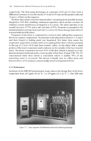
Figure 5.7 lonics Aquamite XXEDR unitfor Doswellcombinedcycle facility