
Page 276 - Membranes for Industrial Wastewater Recovery and Re-Use
P. 276
Case studies 245
55.2 Description of plant
The effluent treatment plant treats all the MDF effluent generated within
the production facility. Excess flow is stored prior to it being pumped into the
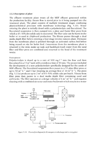
treatment plant. The plant consists of multiple treatment stages combining
physicochemical processes with membrane technology (Fig. 5.10). Water
entering the plant is initially dosed with a polyelectrolyte and flocculated. The
flocculated suspension is then pumped into a plate and frame filter press from
which a 45-50% dry solids cake is recovered. The filter cake can be burnt in the
boiler or re-used in chipboard production. The filtrate passes through a dual
media depth filter before entering a four-stage reverse osmosis plant. Permeate
from the membrane plant is polished through an activated carbon bed before
being reused on site for boiler feed. Concentrate from the membrane plant is
returned to the resin make up tank and backflush/wash water from the sand
filter and filter press are combined and returned to the head of the treatment
works.
Pretreatment
Polyelectrolyte is dosed up to a rate of 500 mg 1-1 into the flow and then
flocculated in a 15 m3 tank with a residence time of 30 min. The project included
the development of a new polyelectrolyte specifically designed for the needs of
MDF effluent. The flocculated suspension then passes to a 55-plate filter press at
up to 50 m3 h-' and 6 bar (treating an average flow of 30 m3 h-l). The press
(Fig. 5.11a) produces up to 2 m3 of 45-50% solids cake per batch. Filtrate from
filter press then passes to a dual media depth filter containing sand and
anthracite. The filter operates at a design velocity of 6 m3 m2 h-l and requires
cleaning with a combined air scour and water backwash which results in a water
Multimedla
depth filter
Waste heat boiler
Carbon ,-, PrOduCtiOn
finer
Concentrate
~
Process water main
Treated water
tank
Figure 5. IO Processflow diagram for Kronospan zero discharge and recovery plant