
Page 286 - Membranes for Industrial Wastewater Recovery and Re-Use
P. 286
Case studies 2 5 5
is constantly looking for ways to reduce its water consumption whilst
maintaining product quality. A number of approaches have been considered to
reduce water demand:
0 Rainwater recycling
0 Well water supply
0 Refrigerator and subfloor condensation recycling
0 Wastewater recycling
The final preference was for wastewater recycling as it provided the most
secure source of water available to the plant. Three applications were identified
for the water including pre washing of product materials, cooling units and floor
washing and boiler feedwater. The projected demand for each application was
40 tonnes day-' which was anticipated to require 140 tonnes day-1 in total of
untreated wastewater to allow for losses during recovery.
5.8.2 Description of plant
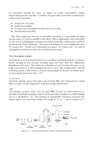
Wastewater is collected and treated in pre existing rotating biological contactors
before passing to the primary aeration tank and then onto the submerged
membrane bioreactor. The permeate is disinfected and stored in the grey water
tank from where it is either pumped for direct use in the cooling tower and the
washing system or diverted to a reverse osmosis plant for further treatment prior
to use as boiler feed water (Fig. 5.1 7).
Pretreatment
The flow initially passes through a pre-existing RBC unit followed by a drum
filter to remove trash components from the sewage and biomass.
MBR
The primary aeration tank (100 m3) and MBR (50 m3) are interconnected to
provide a hydraulic residence time of 24 hours which equates to a BOD loading
rate of 1 kg BOD m-' d-'. The biomass is periodically wasted to maintain the
mixed liquor concentration within the range 8-12 g 1-1 which equates to a
Storage tank I
DlXl"
REC Screen I'aeratm MER
(pe easm) (pre ensting)
Figure 5.17 Processjlow diagram for N-Plant recycling treatment plant