Page 205 -
P. 205

5.4 Future Applications  195
                                                            Layers
                              (a)                                   (b)
                                                                         Laser spot
                                                           Substrate                     Mask
                                                           Protective
                                                                                        a
                                                           Mask
                                                                                       b
                                                           Protective
                                                           Recording
                                                           Protective         R a  d x
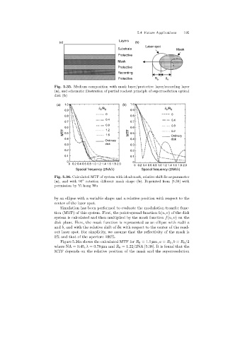
                            Fig. 5.35. Medium composition with mask layer/protective layer/recording layer
                            (a), and schematic illustration of partial readout principle of superresolution optical
                            disk (b)

                             (a)  1.0                         (b)  1.0
                                                  d /R                             d /R
                                 0.9               x  0           0.9              x  0
                                                     0                                0
                                 0.8                              0.8
                                                     0.4                              0.4
                                 0.7                              0.7
                                                     0.8                              0.8
                                 0.6                 1.2          0.6
                                MTF  0.5             1.6         MTF  0.5             Ordinary
                                                                                      0.2
                                 0.4                              0.4                 disk
                                                     Ordinary
                                 0.3                 disk         0.3
                                 0.2                              0.2
                                 0.1                              0.1
                                  0                                0
                                   0 0.2 0.4 0.6 0.8 1.0 1.2 1.4 1.6 1.8 2.0
                                                                   0 0.2 0.4 0.6 0.8 1.0 1.2 1.4 1.6 1.8 2.0
                                       Spacial frequency (2NA/l)       Spacial frequency (2NA/l)
                            Fig. 5.36. Calculated MTF of system with ideal mask, relative shift δx as parameter
                                          ◦
                            (a), and with 90 rotation different mask shape (b). Reprinted from [5.38] with
                            permission by Yi hong Wu

                            by an ellipse with a variable shape and a relative position with respect to the
                            center of the laser spot.
                               Simulation has been performed to evaluate the modulation transfer func-
                            tion (MTF) of this system. First, the point-spread function h(u, v) of the disk
                            system is calculated and then multiplied by the mask function f(u, v)onthe
                            disk plane. Here, the mask function is represented as an ellipse with radii a
                            and b, and with the relative shift of δx with respect to the center of the read-
                            out laser spot. For simplicity, we assume that the reflectivity of the mask is
                            0% and that of the aperture 100%.
                               Figure 5.36a shows the calculated MTF for R 0 =1.1 µm,a = R 0 ,b = R 0 /2
                            where NA = 0.45,λ =0.78 µmand R 0 =1.22/2NA [5.38]. It is found that the
                            MTF depends on the relative position of the mask and the superresolution
   200   201   202   203   204   205   206   207   208   209   210