
Page 202 -
P. 202
192 5 Near Field
p-polarized Without probe
With probe
5
5
0 1.6 mm
0
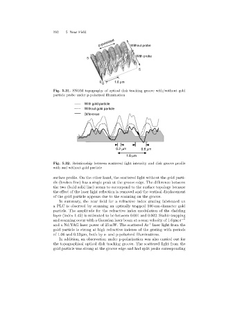
Fig. 5.31. SNOM topography of optical disk tracking groove with/without gold
particle probe under p-polarized illumination
With gold particle
Without gold particle
Difference
0.2 mm 0.6 mm
1.6 mm
Fig. 5.32. Relationship between scattered light intensity and disk groove profile
with and without gold particle
surface profile. On the other hand, the scattered light without the gold parti-
cle (broken line) has a single peak at the groove edge. The difference between
the two (bold solid line) seems to correspond to the surface topology because
the effect of the laser light reflection is removed and the vertical displacement
of the gold particle appears due to the scanning on the groove.
In summary, the near field for a refractive index grating fabricated on
a PLC is observed by scanningan optically trapped 100-nm-diameter gold
particle. The amplitude for the refractive index modulation of the cladding
layer (index 1.45) is estimated to be between 0.001 and 0.002. Stable trapping
and scanningoccur with a Gaussian laser beam at a scan velocity of 1.6 µms −1
+
and a Nd:YAG laser power of 25 mW. The scattered Ar laser light from the
gold particle is strong at high refractive indexes of the grating with periods
of 1.06 and 0.53 µm, both by s- and p-polarized illuminations.
In addition, an observation under p-polarization was also carried out for
the topographical optical disk tracking groove. The scattered light from the
gold particle was strong at the groove edge and had split peaks corresponding