Page 199 -
P. 199

5.3 Experimental Analysis  189
                                  Table 5.4. Conditions to fabricate refractive index grating in PLC
                             core (SiO 2 + GeO 2)index    1.46
                             clad (SiO 2)index            1.45
                             refractive index difference (grating)0.001–0.002 (estimated)
                             phase mask method            source: ArF laser (λ = 193 nm)
                                                          phase mask pitch: 1.06 µm
                                                          energy density per pulse: 1.0Jcm −2  pulse −1
                                                          pulse repetition rate: 50 Hz
                                                          grating pitch (zero-order): 1.06 µm


                                                     Clad               24 mm
                                               Grating
                                                                        6 mm
                                                            Core
                                                     Clad               20 mm
                                                                        1mm
                                                           Si substrate

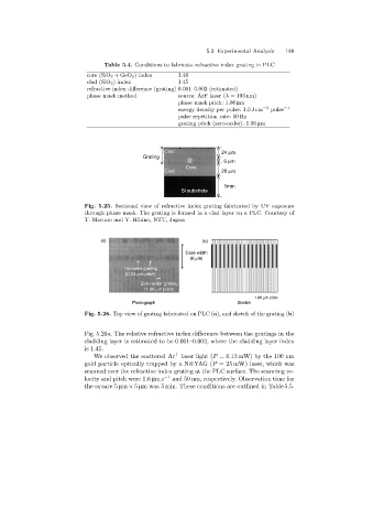
                            Fig. 5.25. Sectional view of refractive index grating fabricated by UV exposure
                            through phase mask. The grating is formed in a clad layer on a PLC. Courtesy of
                            T. Maruno and Y. Hibino, NTT, Japan


                                 (a)                              (b)
                                                            Core width
                                                              (6 mm)
                                        1st-order grating
                                         (0.53 mm pitch)
                                              Zero-order grating
                                               (1.06 mm pitch)
                                                                                  1.06 mm pitch
                                           Photograph                        Sketch
                            Fig. 5.26. Top view of grating fabricated on PLC (a), and sketch of the grating (b)


                            Fig. 5.26a. The relative refractive index difference between the gratings in the
                            claddinglayer is estimated to be 0.001–0.002, where the claddinglayer index
                            is 1.45.
                               We observed the scattered Ar +  laser light (P =0.13 mW) by the 100 nm
                            gold particle optically trapped by a Nd:YAG (P = 25 mW) laser, which was
                            scanned over the refractive index grating at the PLC surface. The scanning ve-
                            locity and pitch were 1.6 µms −1  and 50 nm, respectively. Observation time for
                            the square 5 µm × 5 µm was 5 min. These conditions are outlined in Table 5.5.
   194   195   196   197   198   199   200   201   202   203   204