
Page 196 -
P. 196
186 5 Near Field
(a) (b)
PLC grating
+
Ar laser
Gold
Water particle 150
Sample chamber
mm
CCD
Optical box Coverslip Lasers { l=1060nm
PMT
l=488nm
YAG laser Sample chamber
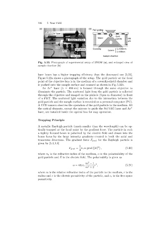
Fig. 5.22. Photograph of experimental setup of SNOM (a), and enlarged view of
sample chamber (b)
laser beam has a higher trapping efficiency than the downward one [5.25].
Figure 5.22a shows a photograph of the setup. The gold particle at the focal
point of the objective lens is in the medium of a coverslip-shield chamber and
is pushed onto the sample surface and scanned as shown in Fig. 5.22b.
An Ar + laser (λ = 488 nm) is focused through the same objective to
illuminate the particle. The scattered light from the gold particle is collected
through the objective and imaged on the pinhole (5 µm in diameter) in front
of a PMT. The scattered light variation due to the interaction between the
gold particle and the sample surface is recorded on a personal computer (PC).
A CCD camera observes the operation of the gold particle in the medium. All
the optical elements, except the mirrors to guide the Nd:YAG laser and Ar +
laser, are installed inside the optical box for easy operation.
Trapping Principle
A metallic Rayleigh particle (much smaller than the wavelength) can be op-
tically trapped at the focal point by the gradient force. The particle in such
a tightly focused beam is polarized by the electric field and drawn into the
beam focus by the large intensity gradients created in both the axial and
transverse directions. The gradient force F grad for the Rayleigh particle is
given by [5.4,5.8]
1 2
F grad = n 1 α grad |E| , (5.20)
4
where n 1 is the refractive index of the medium, α is the polarizability of the
gold particle and E is the electric field. The polarizabiliy is given as
2
m − 1 3
α =4πεε r r , (5.21)
m +2
2
where m is the relative refractive index of the particle to the medium, r is the
radius and ε is the electric permitivity of the particle, and ε r is the free-space
permitivity.