Page 197 -
P. 197

5.3 Experimental Analysis  187
                              Table 5.3. Parameters for calculation of gradient force of Rayleigh particles

                                         refractive index of medium n 1  1.33
                                         refractive index of particle n 2  0.272 + i7.07
                                         objective NA                  1.3
                                         laser power                   20 mW
                                         laser wavelength              1,064 nm
                                         beam profile                 100 nm
                                                                       Gaussian

                                               40
                                              Trapping force F (pN)  30  Fgrad  20 mW


                                               20
                                               10

                                                0         Fscat
                                               -1,000  -500   0     500    1,000
                                                      Distance from focus (nm)

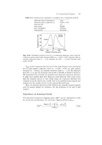
                            Fig. 5.23. Calculated gradient force F grad in transverse direction and in axial di-
                            rection for gold particle with refractive index n 2 =0.272 + i7.07, diameter 100 nm,
                            medium refractive index n 1 =1.33, objective lens NA = 1.3, and Gaussian laser
                            power 20 mW


                               F grad in the transverse direction and in the axial direction were calculated
                            for the gold particle refractive index n 2 =0.272 + i7.07, the gold particle
                            diameter 2r = 100 nm, the medium refractive index n 1 =1.33, the objective
                            lens NA = 1.3, and the Gaussian laser power is 20 mW as listed in Table 5.3.
                            We found from Fig. 5.23 that the gradient force along the transverse direction
                            is eight times greater than that along the axial direction. This result shows
                            that the trapped particle is very stable alongthe transverse direction but
                            unstable alongthe optical axis, which leads to the particle beingtrapped and
                            pushed onto the sample surface by the upward-directed beam.
                               Here, we estimate the forces [5.26] between the optically trapped particle
                            and the sample surface for reference. See the problems at the end of this
                            chapter.


                            Dependence on Scanning Velocity
                            The theoretical transverse trappingpower P  trans  can be expressed in (5.22)
                                                                   pre
                            by takinginto consideration the maximum trappingefficiency Q max

                                                           &                '
                                                                         1
                                                    3πµdvc 1+   9d  T 1  −  H−T
                                                                32
                                              trans
                                            P pre  =                          ,           (5.22)
                                                              n 1 Q max
   192   193   194   195   196   197   198   199   200   201   202