
Page 335 - A Practical Guide from Design Planning to Manufacturing
P. 335
Microprocessor Packaging 305
Main
circuit board
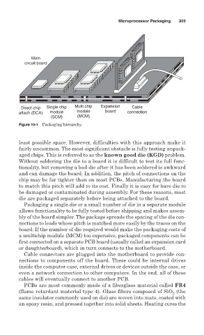
Direct chip Single chip Multi chip Expansion Cable
attach (DCA) module module board connection
(SCM) (MCM)
Figure 10-1 Packaging hierarchy.
least possible space. However, difficulties with this approach make it
fairly uncommon. The most significant obstacle is fully testing unpack-
aged chips. This is referred to as the known good die (KGD) problem.
Without soldering the die to a board it is difficult to test its full func-
tionality, but removing a bad die after it has been soldered is awkward
and can damage the board. In addition, the pitch of connections on the
chip may be far tighter than on most PCBs. Manufacturing the board
to match this pitch will add to its cost. Finally it is easy for bare die to
be damaged or contaminated during assembly. For these reasons, most
die are packaged separately before being attached to the board.
Packaging a single die or a small number of die in a separate module
allows functionality to be fully tested before shipping and makes assem-
bly of the board simpler. The package spreads the spacing of the die con-
nections to leads whose pitch is matched more easily by the traces on the
board. If the number of die required would make the packaging costs of
a multichip module (MCM) too expensive, packaged components can be
first connected on a separate PCB board (usually called an expansion card
or daughterboard), which in turn connects to the motherboard.
Cable connectors are plugged into the motherboard to provide con-
nections to components off the board. These could be internal drives
inside the computer case, external drives or devices outside the case, or
even a network connection to other computers. In the end, all of these
cables will eventually connect to another PCB.
PCBs are most commonly made of a fiberglass material called FR4
(flame retardant material type 4). Glass fibers composed of SiO (the
2
same insulator commonly used on die) are woven into mats, coated with
an epoxy resin, and pressed together into solid sheets. Heating cures the