
Page 198 - Microsensors, MEMS and Smart Devices - Gardner Varadhan and Awadelkarim
P. 198
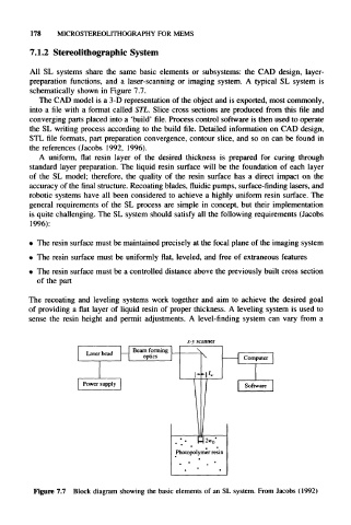
178   MICROSTEREOLITHOGRAPHY FOR    MEMS

      7.1.2  Stereolithographic System


      All  SL  systems  share  the  same  basic  elements  or  subsystems:  the  CAD  design,  layer-
     preparation  functions,  and  a  laser-scanning  or  imaging  system.  A  typical  SL  system  is
      schematically  shown in Figure  7.7.
        The CAD model is a 3-D representation of the object and is exported,  most commonly,
     into a file with a format called  STL.  Slice  cross  sections  are  produced  from  this file and
     converging  parts placed  into a 'build' file. Process control  software is then used to operate
     the  SL writing process  according  to  the build file. Detailed  information on CAD  design,
     STL file formats, part preparation convergence, contour slice,  and  so on  can  be  found  in
     the  references  (Jacobs  1992,  1996).
        A  uniform,  flat  resin  layer  of  the  desired  thickness  is  prepared  for  curing  through
     standard  layer preparation.  The  liquid resin  surface will  be  the  foundation  of  each  layer
     of  the  SL  model;  therefore,  the  quality of  the  resin  surface  has  a  direct  impact  on  the
     accuracy of the final structure. Recoating  blades, fluidic pumps, surface-finding lasers, and
     robotic  systems  have all  been  considered  to  achieve  a highly  uniform  resin surface. The
     general  requirements of  the  SL  process  are  simple  in  concept,  but  their implementation
     is quite challenging. The  SL system should satisfy  all the following  requirements (Jacobs
      1996):


     •  The resin surface must be maintained precisely at the focal plane of the imaging system
     •  The resin  surface  must be uniformly flat,  leveled, and free  of extraneous features
     •  The resin  surface must be a controlled distance above the previously built cross  section
       of  the  part
     The  recoating  and  leveling  systems  work  together  and  aim  to  achieve  the  desired  goal
     of  providing  a flat layer of  liquid resin  of  proper  thickness.  A leveling system is used  to
     sense  the  resin  height  and  permit  adjustments.  A  level-finding  system can  vary  from  a

                                             x-v scanner


                                                  2*0*
                                          Photopolymer resin


      Figure 7.7  Block  diagram  showing  the basic elements of  an  SL system.  From Jacobs  (1992)