
Page 201 - Microsensors, MEMS and Smart Devices - Gardner Varadhan and Awadelkarim
P. 201
SCANNING METHOD 181
microparts and their subsequent electroplating to form metallic microparts have been
reported (Ikuta and Hirowatari 1993; Ikuta et al. 1996; Zissi et al. 1996; Katagi and Naka-
jima 1993; Maruo and Kawata 1997; Bertsch et al. 1997; Nakamoto and Yamaguchi 1996;
Monneret et al. 1999). Functional polymer (e.g. conducting polymer) microparts possess
the unusual characteristics of high flexibility, low density, and high electric conductivity
(Ikuta and Hirowatari 1993). Ceramic microstructures have also been fabricated by MSL
using both structural and functional ceramic materials (Zhang et al. 1999; Jiang et al.
1999). The use of MSL to make both ceramic and metallic microparts is discussed in
Section 7.7.
7.3 SCANNING METHOD
Most MSL equipment developed today are based on the scanning method (Figure 7.8),
which is the method employed in conventional SL and is widely used in the industry. With
the scanning method, a well-focussed laser beam with beam spot size around 1 micron is
directed onto the resin surface to initiate the polymerisation process. A 3-D microstructure
is built up by the repeated scanning of either the light beam or the work piece layer by
layer.
7.3.1 Classical MSL
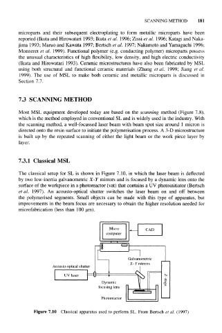
The classical setup for SL is shown in Figure 7.10, in which the laser beam is deflected
by two low-inertia galvanometric X-Y mirrors and is focused by a dynamic lens onto the
surface of the workpiece in a photoreactor (vat) that contains a UV photoinitiator (Bertsch
et al. 1997). An acousto-optical shutter switches the laser beam on and off between
the polymerised segments. Small objects can be made with this type of apparatus, but
improvements in the beam focus are necessary to obtain the higher resolution needed for
rnicrofabrication (less than 100 um).
Galvanometric
X-Y mirrors
Acousto-optical shutter
Dynamic
focusing lens
Photoreactor
Figure 7.10 Classical apparatus used to perform SL. From Bertsch et al. (1997)