
Page 206 - Microsensors, MEMS and Smart Devices - Gardner Varadhan and Awadelkarim
P. 206
186 MICROSTEREOLITHOGRAPHY FOR MEMS
UV light
Optical fibres
_l
i -»•
Stage I 1
r r r - 1
/A r^n r^A • • • £=\ A^
UV polymer i
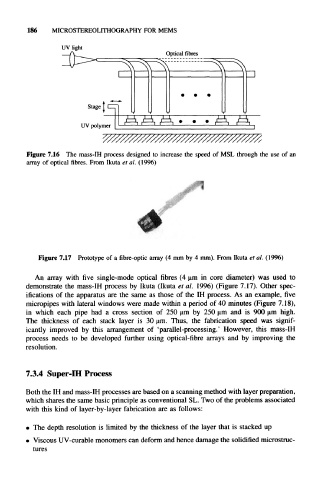
Figure 7.16 The mass-IH process designed to increase the speed of MSL through the use of an
array of optical fibres. From Ikuta el al. (1996)
Figure 7.17 Prototype of a fibre-optic array (4 mm by 4 mm). From Ikuta et al. (19%)
An array with five single-mode optical fibres (4 um in core diameter) was used to
demonstrate the mass-IH process by Ikuta (Ikuta et al. 1996) (Figure 7.17). Other spec-
ifications of the apparatus are the same as those of the IH process. As an example, five
micropipes with lateral windows were made within a period of 40 minutes (Figure 7.18),
in which each pipe had a cross section of 250 u,m by 250 urn and is 900 u.m high.
The thickness of each stack layer is 30 um. Thus, the fabrication speed was signif-
icantly improved by this arrangement of 'parallel-processing.' However, this mass-IH
process needs to be developed further using optical-fibre arrays and by improving the
resolution.
7.3.4 Super-IH Process
Both the IH and mass-IH processes are based on a scanning method with layer preparation,
which shares the same basic principle as conventional SL. Two of the problems associated
with this kind of layer-by-layer fabrication are as follows:
• The depth resolution is limited by the thickness of the layer that is stacked up
• Viscous UV-curable monomers can deform and hence damage the solidified microstruc-
tures