
Page 272 - Microsensors, MEMS and Smart Devices - Gardner Varadhan and Awadelkarim
P. 272
252 MICROSENSORS
Air damping
F(t)
End mass
(a)
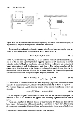
Figure 8.22 (a) A simple microflexure comprising a heavy end or load mass and a thin springlike
support and (b) lumped system equivalent model of the microflexure
The dynamic equation of motion of a simple microflexural structure can be approxi-
mated to a one-dimensional lumped-system model and is given by
mx b mx + k mx = F x(t) (8.27)
where b m is the damping coefficient, k m is the stiffness constant (see Equation (8.23)),
and m is the end mass (ignoring the thin support). Equation (8.27) can readily be solved
using the method of Laplace transforms, provided the three coefficients are constant and
hence independent of both displacement x and time t. The Laplace transform of the
displacement X(s) is related to the Laplace transform of the applied force F(s) by the
characteristic transfer function H(s) of the structure. Hence, the dynamical response of
the structure is described using the complex Laplace parameter s by
1
X(s) = H(s)F(s) = 2 •F(s) (8.28)
ms b ms
The application of a sinusoidal force at a drive frequency (angular) w causes the mass to
oscillate; its characteristic curve, obtained from Equation (8.28), is shown in Figure 8.23.
The resonant frequency w 0 and damping factor £ of the simple microflexural system are
given by
coo = v/fcm/m and £ = b m/2^/k mm (8.29)
Thus, the response or gain 15 of the structure varies with the stiffness and damping of the
structure as well as the nature of the applied load, including a gravitational or inertial
force.
There are a number of different designs of microflexural structures and three of the
basic types - the hammock, folded, and crab-leg - are shown in Figure 8.24. The folding
of the supports changes its effective stiffness and so extends the linear range of deflection.
Here the gain is the ratio of the amplitudes of the output to the input signals.