
Page 298 - Microsensors, MEMS and Smart Devices - Gardner Varadhan and Awadelkarim
P. 298
278 MICROSENSORS
Figure 8.44 Photograph (a) and characteristic (b) of a bipolar magnetotransistor in which both
current difference and injection-modulation effects occur. From Avram et al. (1998)
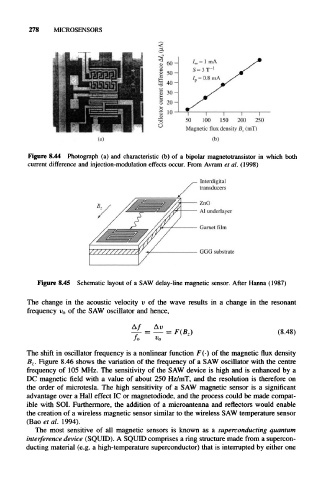
Figure 8.45 Schematic layout of a SAW delay-line magnetic sensor. After Hanna (1987)
The change in the acoustic velocity v of the wave results in a change in the resonant
frequency v 0 of the SAW oscillator and hence,
^L = — = F(B Z) (8.48)
fo v 0
The shift in oscillator frequency is a nonlinear function F(.) of the magnetic flux density
B z. Figure 8.46 shows the variation of the frequency of a SAW oscillator with the centre
frequency of 105 MHz. The sensitivity of the SAW device is high and is enhanced by a
DC magnetic field with a value of about 250 Hz/mT, and the resolution is therefore on
the order of microtesla. The high sensitivity of a SAW magnetic sensor is a significant
advantage over a Hall effect IC or magnetodiode, and the process could be made compat-
ible with SOI. Furthermore, the addition of a microantenna and reflectors would enable
the creation of a wireless magnetic sensor similar to the wireless SAW temperature sensor
(Bao et al. 1994).
The most sensitive of all magnetic sensors is known as a superconducting quantum
interference device (SQUID). A SQUID comprises a ring structure made from a supercon-
ducting material (e.g. a high-temperature superconductor) that is interrupted by either one