
Page 332 - Microsensors, MEMS and Smart Devices - Gardner Varadhan and Awadelkarim
P. 332
312 INTRODUCTION TO SAW DEVICES
Viscous liquid
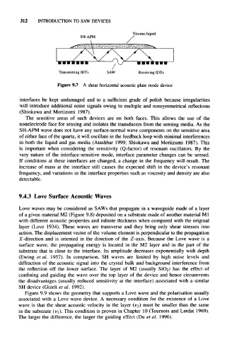
SH-APM
Transmitting IDTs SAW Receiving IDTs
Figure 9.7 A shear horizontal acoustic plate mode device
interfaces be kept undamaged and to a sufficient grade of polish because irregularities
will introduce additional noise signals owing to multiple and nonsymmetrical reflections
(Shiokawa and Moriizumi 1987).
The sensitive areas of such devices are on both faces. This allows the use of the
nonelectrode face for sensing and isolates the transducers from the sensing media. As the
SH-APM wave does not have any surface-normal wave components on the sensitive area
of either face of the quartz, it will oscillate in the feedback loop with minimal interferences
in both the liquid and gas media (Atashbar 1999; Shiokawa and Moriizumi 1987). This
is important when considering the sensitivity (Q-factor) of resonant oscillators. By the
very nature of the interface-sensitive mode, interface parameter changes can be sensed.
If conditions at these interfaces are changed, a change in the frequency will result. The
increase of mass at the interface still causes the expected shift in the device's resonant
frequency, and variations in the interface properties such as viscosity and density are also
detectable.
9.4.3 Love Surface Acoustic Waves
Love waves may be considered as SAWs that propagate in a waveguide made of a layer
of a given material M2 (Figure 9.8) deposited on a substrate made of another material M1
with different acoustic properties and infinite thickness when compared with the original
layer (Love 1934). These waves are transverse and they bring only shear stresses into
action. The displacement vector of the volume element is perpendicular to the propagation
X-direction and is oriented in the direction of the Z-axis. Because the Love wave is a
surface wave, the propagating energy is located in the M2 layer and in the part of the
substrate that is close to the interface. Its amplitude decreases exponentially with depth
(Ewing et al. 1957). In comparison, SH waves are limited by high noise levels and
diffraction of the acoustic signal into the crystal bulk and background interference from
the reflection off the lower surface. The layer of M2 (usually SiO 2) has the effect of
confining and guiding the wave over the top layer of the device and hence circumvents
the disadvantages (usually reduced sensitivity at the interface) associated with a similar
SH device (Gizeli et al. 1992).
Figure 9.9 shows the geometry that supports a Love wave and the polarisation usually
associated with a Love wave device. A necessary condition for the existence of a Love
wave is that the shear acoustic velocity in the layer (v 2 ) must be smaller than the same
in the substrate (v 1). This condition is proven in Chapter 10 (Tournois and Lardat 1969).
The larger the difference, the larger the guiding effect (Du et al. 1996).