
Page 330 - Microsensors, MEMS and Smart Devices - Gardner Varadhan and Awadelkarim
P. 330
310 INTRODUCTION TO SAW DEVICES
Using a second set of matched IDTs, the electromechanical wave can be received and
converted back into an electrical signal. Therefore, using a transmitting and receiving set
of electrodes connected in a feedback loop of a suitable feedback amplifier, sustainable
oscillation can be achieved (Avramov 1989). The IDT finger spacing d relates to the
frequency of the device (see Section 9.2).
The electrode structures are usually made from a combination of an ultrathin 10–20 nm
layer of chromium (Cr), followed by a thin layer of approximately 150 nm of gold (Au) or
a thin layer of aluminum (Al) of a standard thickness of 150 nm (Atashbar 1999). In the
case of a Cr—Au electrode, the chromium not only forms an ohmic contact with the quartz
but also acts as an adhesion layer for the gold. Gold is used as the final interface to the
environment because of its relatively inert characteristics compared with chromium and
other metals. In the case of the aluminum electrode, the adhesion between aluminum and
quartz is sufficiently high to prevent the need for a chromium layer to link the substrate
to the metallisation layer.
SAW devices typically operate in the range of 30 MHz to 1 GHz on ST-quartz and
various cuts of lithium niobate. There are two ways to perturb the device. One is to
perturb the electrical field above the propagation path length and the other is to perturb
the actual mechanical wave traveling across the propagation path. The latter is followed
in this case. The perturbing agent tends to alter the characteristics of the wave that is
propagated between the two IDTs, leading to a change in the phase or the frequency of
the wave, which may then be measured by suitable application of a measurement device
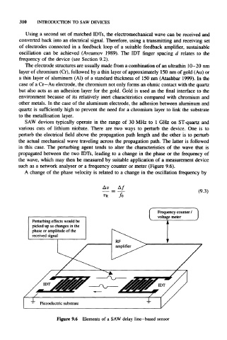
such as a network analyser or a frequency counter or meter (Figure 9.6).
A change of the phase velocity is related to a change in the oscillation frequency by
Au
(9.3)
/o
[ Frequency c o u n t e r |
voltage
meter
Perturbing effects would be
picked up as changes in the
phase or amplitude of the
received signal
Figure 9.6 Elements of a SAW delay line-based sensor