
Page 327 - Microsensors, MEMS and Smart Devices - Gardner Varadhan and Awadelkarim
P. 327
THE PIEZOELECTRIC EFFECT 307
3. The model of the acoustic wave can be changed, for example, from compressional to
shear, or the angle of propagation can be varied.
9.3.1 Interdigital Transducers in SAW Devices
Acoustic waves propagating along the surface of a piezoelectric material provide a means
of implementing a variety of signal-processing devices at frequencies ranging from several
MHz to a few GHz (Campbell 1998). The IDT provides the cornerstone of SAW tech-
nology. Its function is to convert electrical energy into mechanical energy, and vice versa,
for generating and detecting the SAW.
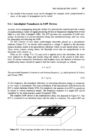
An IDT consists of two metal comb-shaped electrodes placed on a piezoelectric
substrate (Figure 9.2). An electric field created by a voltage V applied to the electrodes
induces dynamic strains in the piezoelectric substrate, which, in turn, launch elastic waves.
These waves contain, among others, the Rayleigh waves that run perpendicular to the
electrodes with velocity vR.
When an AC voltage V(t) [V o exp(jwt)] is applied across the electrodes, the stress
wave induced by the finger pair travels along the surface of the crystal in both direc-
tions. To ensure constructive interference and in-phase stress, the distance d between two
neighbouring fingers should be equal to half the elastic wavelength A.R whence
d = A R /2 (9.1)
The associated frequency is known as synchronous frequency, f 0, and is given by (d' Amico
and Verona 1989)
f 0 = V R A R (9.2)
At this frequency, the transducer efficiency in converting electrical energy to acoustical,
or vice versa, is maximised. The exact calculation of the piezoelectric field driven by the
IDT is rather elaborate (Smith 1976). For simplicity, the analysis of an IDT is carried out
by means of various numerical models. The frequency response of a single IDT can be
simplified by the delta-function model (Campbell 1998).
The simplest SAW device is the nondispersive delay line depicted in Figure 9.3. One
IDT is connected to an electrical source and the other to a detector. The source IDT sets
Figure 9.2 Finger-spacings and their role in the determination of the acoustic wavelength