
Page 331 - Microsensors, MEMS and Smart Devices - Gardner Varadhan and Awadelkarim
P. 331
ACOUSTIC WAVES 311
where Au is the change in the velocity of the wave and Af is the corresponding
frequency change. v R is the propagation velocity of the Rayleigh wave and f 0 is the
design frequency.
The particle displacement components and the quasi-static electrical potential of the
SAW are described in Section 10.4 for both Rayleigh waves and Love waves.
9.4.2 Shear Horizontal Acoustic Waves
The selection of a different crystal cut can yield SH surface waves instead of vertical
Rayleigh waves (Nakamura et al. 1977). The particle displacements of this type of wave
are transverse to the wave propagation direction and parallel to the plane of the surface.
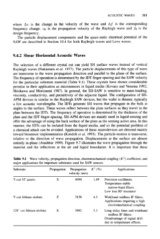
The frequency of operation is determined by the IDT finger-spacing and the SAW velocity
for the particular substrate material (Table 9.1). These crystals have shown considerable
promise in their application as microsensors in liquid media (Kovacs and Venema 1992;
Shiokawa and Moriizumi 1987). In general, the SH-SAW is sensitive to mass-loading,
viscosity, conductivity, and permittivity of the adjacent liquid. The configuration of SH-
APM devices is similar to the Rayleigh SAW devices, but the wafer is thinner, typically
a few acoustic wavelengths. The IDTs generate SH waves that propagate in the bulk at
angles to the surface. These waves reflect between the plate surfaces as they travel in the
plate between the IDTs. The frequency of operation is determined by the thickness of the
plate and the IDT finger-spacing. SH-APM devices are mainly used in liquid-sensing and
offer the advantage of using the back surface of the plate as the sensing active area. In this
manner, the IDTs can be isolated from the liquid media, and so the potential problem of
a chemical attack can be avoided. Applications of these microdevices are directed mainly
toward biosensor implementation (Kondoh et al. 1993). The particle motion is transverse,
relative to the direction of wave propagation. Displacements at the surface are almost
entirely in-plane (Atashbar 1999). Figure 9.7 illustrates the wave propagation through the
material and the reflections at the air and liquid boundaries. It is important that these
2
Table 9.1 Wave velocity, propagation direction, electromechanical coupling (K ) coefficient, and
major applications for important substrates used for SAW sensors
2
Substrate Propagation Propagation K (%) Applications
velocity (m/s)
Y-cut ST quartz X 4990 1.89 Precision oscillators.
Temperature-stable
narrow-band filters.
Low loss RF resonator
Y-cut lithium niobate 3158 4.5 Wideband midloss IF filters.
Applications requiring a high
electromechanical coupling
128° cut lithium niobate X 3992 5.3 Long delay lines and wideband
midloss IF filters.
Disadvantage of signal drift
due to temperature effects.