
Page 328 - Microsensors, MEMS and Smart Devices - Gardner Varadhan and Awadelkarim
P. 328
308 INTRODUCTION TO SAW DEVICES
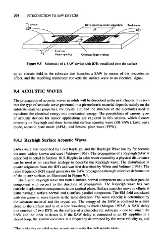
To source IDTs centre to centre separation To detector
— Uniform
finger spacing Constant finger overlap
Figure 9.3 Schematic of a SAW device with IDTs metallised onto the surface
up an electric field in the substrate that launches a SAW by means of the piezoelectric
effect, and the receiving transducer converts the surface wave to an electrical signal.
9.4 ACOUSTIC WAVES
The propagation of acoustic waves in solids will be described in the next chapter. It is seen
that the type of acoustic wave generated in a piezoelectric material depends mainly on the
substrate material properties, the crystal cut, and the structure of the electrodes used to
transform the electrical energy into mechanical energy. The possibilities of various types
of acoustic devices for sensor applications are explored in this section, which focuses
primarily on Rayleigh and shear horizontal surface acoustic wave (SH-SAW), Love wave
mode, acoustic plate mode (APM), and flexural plate wave (FPW).
9.4.1 Rayleigh Surface Acoustic Waves
SAWs were first described by Lord Rayleigh, and the Rayleigh Wave has by far become
the most widely known and used (Viktorov 1967). The propagation of a Rayleigh SAW is
described in detail in Section 10.5. Ripples in calm water caused by a physical disturbance
can be used as an excellent analogy to describe the Rayleigh wave. The disturbance in
quartz originates from the IDTs and was first described by White and Voltmer (1965). The
radio frequency (RF) signal generates the SAW propagation through selective deformation
of the quartz surface, as illustrated in Figure 9.4.
The elastic Rayleigh wave has both a surface-normal component and a surface-parallel
component with respect to the direction of propagation. The Rayleigh wave has two
particle displacement components in the sagittal plane. Surface particles move in elliptical
paths having a surface-normal and a surface-parallel component. The EM field associated
with the acoustic wave travels in the same direction. The wave velocity is determined by
the substrate material and the crystal cut. The energy of the SAW is confined to a zone
4
close to the surface and is of a few wavelengths thick (Morgan 1978) . A SAW delay
line consists of two IDTs on the surface of a piezoelectric substrate - one to launch the
SAW and the other to detect it. If the SAW delay is connected to an RF amplifier in a
closed loop, the system oscillates at a frequency determined by the wave velocity v R and
4
That is why they are called surface acoustic waves rather than bulk acoustic waves.