
Page 359 - Microsensors, MEMS and Smart Devices - Gardner Varadhan and Awadelkarim
P. 359
ANALOGUE (AMPLITUDE) MEASURING SYSTEM 339
1. Far too time-consuming
2. Restricted, as only one acoustic sensor can be measured at a time
3. Allows only steady state measurements; no dynamic response measurements are
possible
4. Very expensive to operate, in terms of both the instrument price and the need for highly
qualified personnel
5. Unable to offer remote-sensing
6. Too cumbersome and not portable
Nevertheless, there are instances in which it is useful to use a network analyser to under-
stand an IDT-SAW problem. For example, most of the work described here on the device
referred to previously as an ice microsensor has been more of a characterisation study,
so it is sensible to employ a network analyser in order to measure the relevant phase
3
difference parameters . This is despite the fact that the network analyser carries with it
all the relevant disadvantages just listed.
Before choosing the configuration to employ, the following question should always be
asked:
'What is the most practical and appropriate form of instrumentation or system to be used
for measuring and analyzing acoustic-based microsensors?'
Wohltjen and Dessy (1979) answered the question by describing three general methods
for measuring the response of a SAW microsensor - amplitude, phase, or frequency
measurements. The following three sections provide typical examples of such measuring
systems (Wohltjen and Dessy 1979) based on these methods.
11.4 ANALOGUE (AMPLITUDE) MEASURING SYSTEM
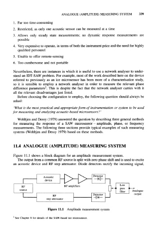
Figure 11.1 shows a block diagram for an amplitude measurement system.
The output from a common RF source is split with zero phase shift and is used to excite
an acoustic device and RF step attenuator. Diode detectors rectify the incoming signal,
Acoustic
device
RF RF amplifiers
source LJ Analogue
RF Detector output
step attenuator
Figure 11.1 Amplitude measurement system
3
See Chapter 8 for details of the SAW-based ice microsensor.