
Page 362 - Microsensors, MEMS and Smart Devices - Gardner Varadhan and Awadelkarim
P. 362
342 IDT MICROSENSOR PARAMETER MEASUREMENT
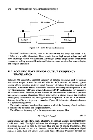
Figure 11.4 SAW device oscillator circuit
Non-AGC oscillator circuits, such as the Brukenstein and Shay (see Smith el al.
(1969)), are a viable alternative. These circuits feature high output voltage and will
drive under high viscous load conditions. Advantages of their design include fewer circuit
components making less-possible noise and drift sources and are, therefore a much simpler
and compact alternative.
11.7 ACOUSTIC WAVE SENSOR OUTPUT FREQUENCY
TRANSLATION
Typically, the unperturbed resonant frequency of acoustic resonators used for sensing
applications ranges between 30 and 300 MHz for SAW devices. As sensors, typical
sensing effects constitute relatively small frequency deviations from their unperturbed
resonance, from several kHz to a few MHz. However, measuring such frequencies in the
very high frequency (VHF) and ultrahigh frequency (UHF) bands requires very expensive
RF instrumentation. Therefore, moves from the RF spectrum down to the audio spectrum
has proved a popular alternative. This is achieved by a mixing process that involves
heterodyning the reference and sensing oscillator frequencies. A low-pass filter ensures
that only the difference frequency is passed on. Figure 11.5 shows the schematic diagram
of a typical mixing circuit.
The circuit consists of a dual-oscillator system in which the frequency of each oscillator
is controlled by reference and sample resonators.
The difference frequency f is the output from the low-pass filter
= (f ref — f sample) (11–1)
Digital mixing circuits offer a viable alternative to classical analogue circuit techniques
(Smith et al. 1969). The digital technique has advantages over analogue methods in that
it removes the need for both the low-pass filter and the RF mixing transformer. This
substantially lowers cost and size. However, irrespective of whether analogue or digital
mixing is used, there will always exist some finite difference frequency between the