
Page 361 - Microsensors, MEMS and Smart Devices - Gardner Varadhan and Awadelkarim
P. 361
FREQUENCY MEASUREMENT SYSTEM 341
11.6 FREQUENCY MEASUREMENT SYSTEM
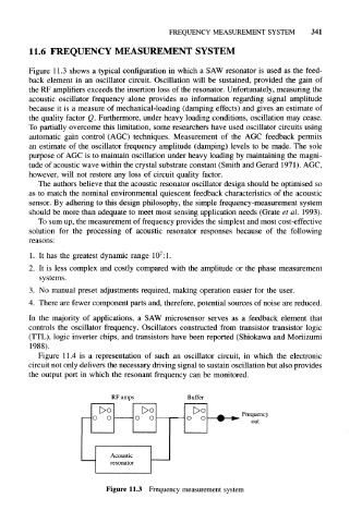
Figure 11.3 shows a typical configuration in which a SAW resonator is used as the feed-
back element in an oscillator circuit. Oscillation will be sustained, provided the gain of
the RF amplifiers exceeds the insertion loss of the resonator. Unfortunately, measuring the
acoustic oscillator frequency alone provides no information regarding signal amplitude
because it is a measure of mechanical-loading (damping effects) and gives an estimate of
the quality factor Q. Furthermore, under heavy loading conditions, oscillation may cease.
To partially overcome this limitation, some researchers have used oscillator circuits using
automatic gain control (AGC) techniques. Measurement of the AGC feedback permits
an estimate of the oscillator frequency amplitude (damping) levels to be made. The sole
purpose of AGC is to maintain oscillation under heavy loading by maintaining the magni-
tude of acoustic wave within the crystal substrate constant (Smith and Gerard 1971). AGC,
however, will not restore any loss of circuit quality factor.
The authors believe that the acoustic resonator oscillator design should be optimised so
as to match the nominal environmental quiescent feedback characteristics of the acoustic
sensor. By adhering to this design philosophy, the simple frequency-measurement system
should be more than adequate to meet most sensing application needs (Grate et al. 1993).
To sum up, the measurement of frequency provides the simplest and most cost-effective
solution for the processing of acoustic resonator responses because of the following
reasons:
7
1. It has the greatest dynamic range 10 :1.
2. It is less complex and costly compared with the amplitude or the phase measurement
systems.
3. No manual preset adjustments required, making operation easier for the user.
4. There are fewer component parts and, therefore, potential sources of noise are reduced.
In the majority of applications, a SAW microsensor serves as a feedback element that
controls the oscillator frequency. Oscillators constructed from transistor transistor logic
(TTL), logic inverter chips, and transistors have been reported (Shiokawa and Moriizumi
1988).
Figure 11.4 is a representation of such an oscillator circuit, in which the electronic
circuit not only delivers the necessary driving signal to sustain oscillation but also provides
the output port in which the resonant frequency can be monitored.
RF amps Buffer
Oo
o o Frequency
*" out
Acoustic
resonator
Figure 11.3 Frequency measurement system