
Page 360 - Microsensors, MEMS and Smart Devices - Gardner Varadhan and Awadelkarim
P. 360
340 IDT MICROSENSOR PARAMETER MEASUREMENT
producing a negative direct current (DC) level from the acoustic device and a positive
DC level from the attenuator arm. A potentiometer is used to set the signal to zero for
the unperturbed acoustic resonator. A subsequent low-pass filter restricts the bandwidth
of the resultant analogue output signal.
11.5 PHASE MEASUREMENT SYSTEM
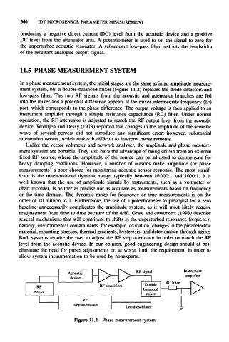
In a phase measurement system, the initial stages are the same as in an amplitude measure-
ment system, but a double-balanced mixer (Figure 11.2) replaces the diode detectors and
low-pass filter. The two RF signals from the acoustic and attenuator branches are fed
into the mixer and a potential difference appears at the mixer intermediate frequency (IF)
port, which corresponds to the phase difference. The output voltage is then applied to an
instrument amplifier through a simple resistance capacitance (RC) filter. Under normal
operation, the RF attenuator is adjusted to match the RF output level from the acoustic
device. Wohltjen and Dessy (1979) reported that changes in the amplitude of the acoustic
wave of several percent did not introduce any significant error; however, substantial
attenuation occurs, which makes it difficult to interpret measurements.
Unlike the vector voltmeter and network analyser, the amplitude and phase measure-
ment systems are portable. They also have the advantage of being driven from an external
fixed RF source, where the amplitude of the source can be adjusted to compensate for
heavy damping conditions. However, a number of reasons make amplitude (or phase
measurements) a poor choice for monitoring acoustic sensor response. The most signif-
icant is the much-reduced dynamic range, typically between 10000:1 and 1000:1. It is
well known that the use of amplitude signals by instruments, such as a voltmeter or
chart recorder, is neither as precise nor as accurate as measurements based on frequency
or the time domain. The dynamic range for frequency or time measurements is on the
order of 10 million to 1. Furthermore, the use of a potentiometer to preadjust for a zero
baseline unnecessarily complicates the amplitude system, as it will most likely require
readjustment from time to time because of the drift. Grate and coworkers (1993) describe
several mechanisms that will contribute to shifts in the unperturbed resonance frequency,
namely, environmental contaminants, for example, oxidation, changes in the piezoelectric
material, mounting stresses, thermal gradients, hysteresis, and deterioration through aging.
Both systems require the user to adjust the RF step attenuator in order to match the RF
level from the acoustic device. In our opinion, good engineering design should at best
eliminate the need for preset adjustments or, at worst, limit the requirement, in order to
allow system instrumentation to be used by nonexperts.
PV^ RF signal Instrument
Acoustic amplifier
device 1
RF RF amplifiers Double RC 1 filter K. 1^
,
1
source balanced
mixer
RF 1
step attenuator
Local oscillator
Figure 11.2 Phase measurement system