
Page 207 - Modeling of Chemical Kinetics and Reactor Design
P. 207
Reaction Rate Expression 177
reactor design. This is because knowledge of the mechanism will make
if possible to fit the experimental data to a theoretical rate expression,
which will be more reliable than an empirical fit. Also, the mechanism
may require some modifications and optimization for the final design.
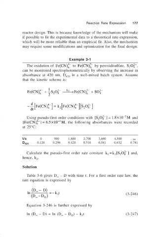
Example 3-1
−
(
(
−
2−
4
3
The oxidation of Fe CN) to Fe CN) by peroxidisulfate, SO ,
6 6 2 8
can be monitored spectrophotometrically by observing the increase in
absorbance at 420 nm, D 420 in a well-mixed batch system. Assume
that the kinetic scheme is:
Fe CN) 4 − + 1 S O 2 − → ( 3 − + SO 2 −
(
Fe CN)
k 2
6 2 8 6 4
2
[
− d [ Fe (CN ) 4 − ] = k Fe (CN ) 4 − ][ S O 2 8 − ]
2
2
dt 6 6
×
Using pseudo-first order conditions with [SO 2− ] = . 18 10 − 2 M and
8
2
4−
×
[Fe (CN ) ] = . 65 10 − 4 M, the following absorbances were recorded
6
at 25°C:
t/s 0 900 1,800 2,700 3,600 4,500 ∞
D 0.120 0.290 0.420 0.510 0.581 0.632 0.781
420
2−
Calculate the pseudo-first order rate constant k = k S O ] and,
[
8
2
2
1
hence, k .
2
Solution
Table 3-6 gives D – D with time t. For a first order rate law, the
∞
rate equation is expressed by
( D − D)
ln ∞ =− kt
( D − D ) 1 (3-246)
∞
O
Equation 3-246 is further expressed by
ln (D – D) = ln (D – D ) – k t (3-247)
∞
∞
O
1