
Page 24 - Modeling of Chemical Kinetics and Reactor Design
P. 24
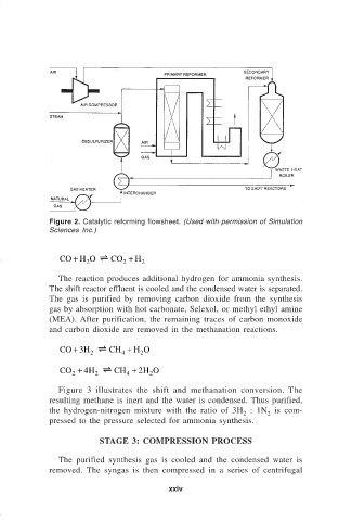
Figure 2. Catalytic reforming flowsheet. (Used with permission of Simulation
                              Sciences Inc.)


                                 CO H O [
                                    +  2      CO +  H 2
                                                 2
                                The reaction produces additional hydrogen for ammonia synthesis.
                              The shift reactor effluent is cooled and the condensed water is separated.
                              The gas is purified by removing carbon dioxide from the synthesis
                              gas by absorption with hot carbonate, Selexol, or methyl ethyl amine
                              (MEA). After purification, the remaining traces of carbon monoxide
                              and carbon dioxide are removed in the methanation reactions.

                                 CO + 3
                                       H  [  CH +  H O
                                                4
                                                     2
                                        2
                                 CO +
                                    2  4 H  [  CH +  2 H O
                                          2
                                                  4
                                                        2
                                Figure 3 illustrates the shift and methanation conversion.  The
                              resulting methane is inert and the water is condensed. Thus purified,
                              the hydrogen-nitrogen mixture with the ratio of 3H  : 1N  is com-
                                                                               2      2
                              pressed to the pressure selected for ammonia synthesis.
                                           STAGE 3: COMPRESSION PROCESS

                                The purified synthesis gas is cooled and the condensed water is
                              removed.  The syngas is then compressed in a series of centrifugal

                                                            xxiv