
Page 26 - Modeling of Chemical Kinetics and Reactor Design
P. 26
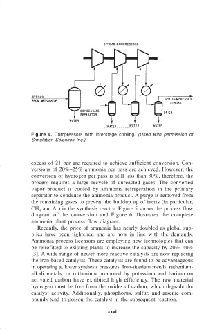
Figure 4. Compressors with interstage cooling.  (Used with permission of
                              Simulation Sciences Inc.)


                              excess of 21 bar are required to achieve sufficient conversion. Con-
                              versions of 20%–25% ammonia per pass are achieved. However, the
                              conversion of hydrogen per pass is still less than 30%, therefore, the
                              process requires a large recycle of unreacted gases.  The converted
                              vapor product is cooled by ammonia refrigeration in the primary
                              separator to condense the ammonia product. A purge is removed from
                              the remaining gases to prevent the buildup up of inerts (in particular,
                              CH  and Ar) in the synthesis reactor. Figure 5 shows the process flow
                                 4
                              diagram of the conversion and Figure 6 illustrates the complete
                              ammonia plant process flow diagram.
                                Recently, the price of ammonia has nearly doubled as global sup-
                              plies have been tightened and are now in line with the demands.
                              Ammonia process licensors are employing new technologies that can
                              be retrofitted to existing plants to increase the capacity by 20%–40%
                              [3]. A wide range of newer more reactive catalysts are now replacing
                              the iron-based catalysts. These catalysts are found to be advantageous
                              in operating at lower synthesis pressures. Iron-titanium metals, ruthenium-
                              alkali metals, or ruthenium promoted by potassium and barium on
                              activated carbon have exhibited high efficiency.  The raw material
                              hydrogen must be free from the oxides of carbon, which degrade the
                              catalyst activity. Additionally, phosphorus, sulfur, and arsenic com-
                              pounds tend to poison the catalyst in the subsequent reaction.

                                                            xxvi