
Page 27 - Modeling of Chemical Kinetics and Reactor Design
P. 27
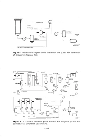
Figure 5. Process flow diagram of the conversion unit. (Used with permission
                              of Simulation Sciences Inc.)


                              Figure 6.  A complete ammonia plant process flow diagram.  (Used with
                              permission of Simulation Sciences Inc.)

                                                            xxvii