
Page 25 - Modeling of Chemical Kinetics and Reactor Design
P. 25
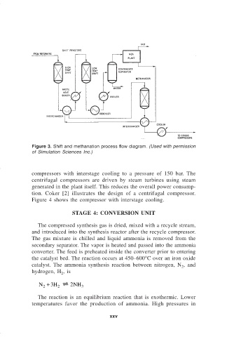
Figure 3. Shift and methanation process flow diagram. (Used with permission
                              of Simulation Sciences Inc.)


                              compressors with interstage cooling to a pressure of 150 bar.  The
                              centrifugal compressors are driven by steam turbines using steam
                              generated in the plant itself. This reduces the overall power consump-
                              tion. Coker [2] illustrates the design of a centrifugal compressor.
                              Figure 4 shows the compressor with interstage cooling.

                                              STAGE 4: CONVERSION UNIT

                                The compressed synthesis gas is dried, mixed with a recycle stream,
                              and introduced into the synthesis reactor after the recycle compressor.
                              The gas mixture is chilled and liquid ammonia is removed from the
                              secondary separator. The vapor is heated and passed into the ammonia
                              converter. The feed is preheated inside the converter prior to entering
                              the catalyst bed. The reaction occurs at 450–600°C over an iron oxide
                              catalyst.  The ammonia synthesis reaction between nitrogen, N , and
                                                                                         2
                              hydrogen, H , is
                                         2
                                 N +  3 H  [  2 NH
                                   2    2        3

                                The reaction is an equilibrium reaction that is exothermic. Lower
                              temperatures favor the production of ammonia. High pressures in

                                                             xxv