
Page 136 - Modern Control Systems
P. 136
110 Chapter 2 Mathematical Models of Systems
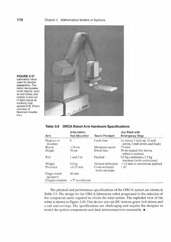
FIGURE 2.47
Laboratory robot
used for sample
preparation. The
robot manipulates
small objects, such
as test tubes, and
probes in and out
of tight places at
relatively high
speeds [15]. (Photo
courtesy of
Beckman Coulter,
Inc.)
Table 2.9 ORCA Robot Arm Hardware Specifications
Articulated, Joy Stick with
Arm Rail-Mounted Teach Pendant Emergency Stop
Degrees of 6 Cycle lime 4 s (move 1 inch up, 12 inch
freedom across, 1 inch down, and back)
Reach ±54 cm Maximum speed 75 cm/s
Height 78 cm Dwell time 50 ms typical (for moves
within a motion)
Rail 1 and 2 m Payloacl 0.5 kg continuous, 2.5 kg
transient (with restrictions)
Weight 8.0 kg Vertical deflection <1.5 mm at continuous payload
Precision ±0.25 mm Cross-sectional lm 2
work envelope
Finger travel 40 mm
(gripper)
Gripper rotation ±77 revolutions
The physical and performance specifications of the ORCA system are shown in
Table 2.9. The design for the ORCA laboratory robot progressed to the selection of
the component parts required to obtain the total system. The exploded view of the
robot is shown in Figure 2.48. This device uses six DC motors, gears, belt drives, and
a rail and carriage. The specifications are challenging and require the designer to
model the system components and their interconnections accurately. •